Validating fundamentals: Circular cylinder in an airflow - Femto Engineering - Femto Engineering

Validating fundamentals: Circular cylinder in an airflow

In this article we will validate a fundamental simulation, namely a circular cylinder in an airflow. The simulation in this article is validated using the data from experimental research by J.-C. Bera et. al. [1].

Set-up

The circular cylinder used in the current simulations has a diameter of 10 cm. Air flows into the domain with a velocity of 20 m/s and a turbulence intensity of 0.3%. Using these settings, the experiments showed a drag coefficient of 0.55 and a lift coefficient of -0.03.

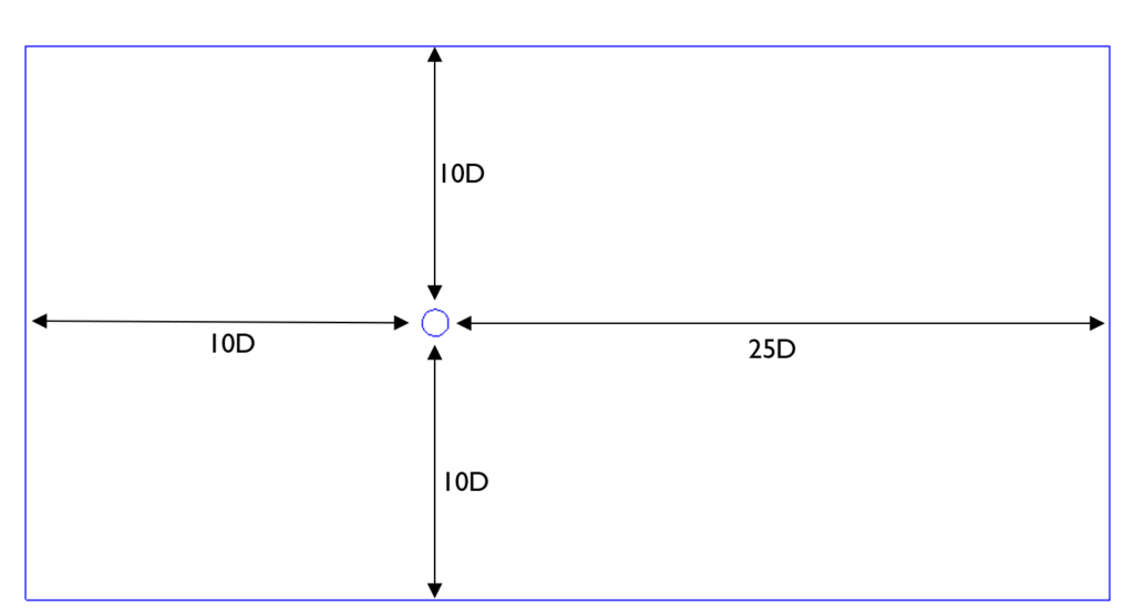
The domain around the body is described in the image below. The size of the domain is created based on the diameter of the pipe. The depth of the domain is 1 diameter wide, modelling the pipe in quasi-2D.

Figure 1: domain

Figure 1: domain

Mesh

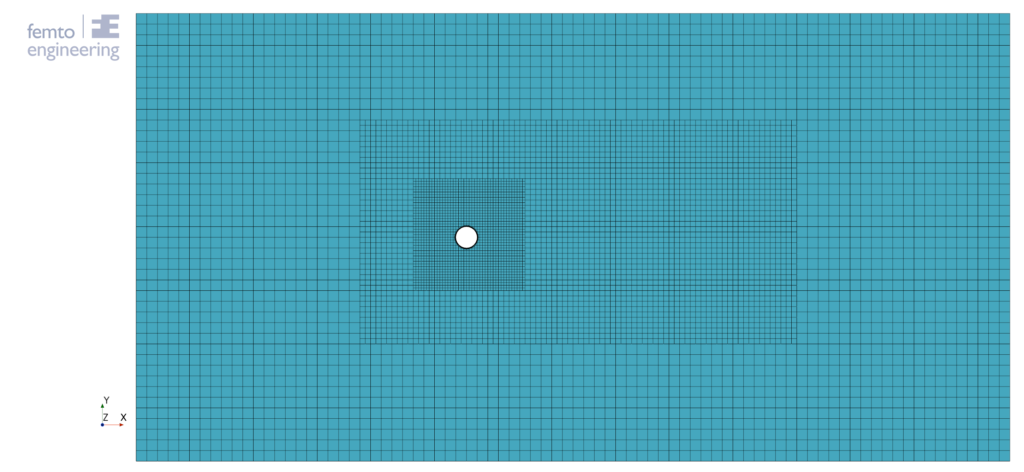
Four meshes are generated to perform a mesh refinement study. In the image below the coarse mesh is shown. In the mesh, two refinement boxes are generated to account for the eddies coming from the pipe. Every mesh reduces the base size by a factor of 2, starting with a base size of 10cm for the coarse mesh and ending with a base size of 1.25cm for the finest mesh.

Figure 2: coarse mesh

Figure 2: coarse mesh

Physics

For this simulation one phase, namely air, is used. The turbulence realistic k-ε  two layer model is used, with a turbulence intensity of 0.3% and a reference velocity of 20m/s.

Mesh refinement study

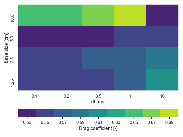
A mesh and time refinement study has been performed to find the closest approximation in drag coefficient compared to the test. The results of this study can be found in figure 3, The experimental drag coefficient is shown by the 0.55 box in the legend. From this figure it can be concluded that a maximum base size of 2.5cm is needed with a maximum timestep of 1ms. This leads to an error in drag coefficient of 2.5%. This error can be lowered to a minimum value of 1% by using the finest mesh with a timestep of 0.2ms or lower. However, an error of 2.5% is deemed acceptable for further study.

figure 3: mesh and time refinement study

figure 3: mesh and time refinement study

Bibliography

[1]
J.-C. Bera, M. Michard, M. Sunyach and G. Comte-Bellot, “Changing lift and drag by jet oscillation: experiments on a circular cylinder with turbulent separation,” European Journal of Mechanics – B/Fluids, vol. 19, pp. 575-595, 2000.

January 11, 2022
our services

engineering consultancy

We have a reliable and flexible team that can work alongside you to thoroughly assess the structural integrity of your products. Let us explain how FEA & CFD can add value to your work.

Read more

software

The software you use should get the job done. The analysis and simulation solutions from our Partner, Siemens Digital Industries Software will do just that. We offer related advice, support and training too.
Read more

R&D

Through research and innovation, we support our clients to be at the forefront of new technology. This is why we invest in R&D and work closely with industry leading research institutes and universities.
Read more

get in touch

Do you need more information or want to discuss your project? Reach out to us anytime and we’ll happily answer your questions.

about us

At Femto Engineering we help companies achieve their innovation ambitions with engineering consultancy, software, and R&D.
We are Siemens DISW Expert Partner for Simcenter Femap, Simcenter 3D, Simcenter Amesim, Simcenter STAR-CCM+ and SDC verifier. Get in touch and let us make CAE work for you.

Privacy policy

×

Be ahead in FEA & CFD

Sign up for our newsletter to get free resources, news and updates monthly in your inbox. Share in our expertise!

Hello world.

This is a sample box, with some sample content in it.

This is a link

Hello world.

This is a sample box, with some sample content in it.

This is a link