Fatigue strength calculation according to the FKM guideline using FEM
When you have dynamic loads on your construction it is wise to check the model on fatigue to avoid fatigue cracks. A common method to do that is using the FKM Guideline.
When you have dynamic loads on your construction it is wise to check the model on fatigue to avoid fatigue cracks. A common method to do that is using the FKM Guideline.
To evaluate a component or an assembly for fatigue strength according to the FKM guideline, previously calculated hotspots often must be examined in detail in FEM programs. This does mean a lot of work, because you need to import results for the elements you want to investigate in other programs to do the check.
To simplify the work here and to be able to present the results clearly, Femto Engineering uses SDC Verifier, which has been developed specifically for evaluation according to various standards.
In addition to the usual properties that must be assigned to the materials and geometries, factors and parameters of the FKM guideline and material or welding seam grades such as FAT classes now have to be assigned to the elements. The assignments can easily be done in an interface made for all the input you need.
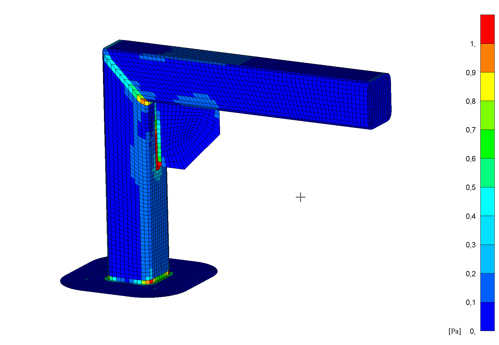
With the tensile strengths or FAT classes and the specified factors, parameters and Wöhler curves stored in the FKM guideline, the program calculates the maximum stress amplitude that can be tolerated in order to be fatigue-resistant according to the FKM guideline. The formulas which are given from the guideline are included in the program and calculated automatically.
The following figure shows this using a small welded assembly that is alternately loaded in the vertical direction [Pa].
![Figure 1Maximum bearable stress amplitude [Pa].](https://www.femto.eu/wp-content/uploads/2022/08/MicrosoftTeams-image-28.png)
Figure 1 Maximum bearable stress amplitude [Pa].
This assembly is just to show the work progress. Of course, you can use it for all welded and even unwelded constructions, just as cranes or shafts.Based on these calculated permissible stresses, a safety factor and the calculated existing stresses, the program now calculates the maximum degree of utilization (occurring stress/allowable stress) per element, which can afterwards be plotted:

Figure 2 Utilisation factor for fatigue strength according to FKM
You can see in the picture some red areas in a weld. Red areas do mean, that the degree of utilization is above 1, which means you probably will get fatigue cracks in these areas.
In addition to a calculation of the fatigue strength, static calculations according to FKM and operational strength analyses according to FKM are of course also possible.
At Femto Engineering, we always want to make sure we get the most out of our simulations. As seen in Figure 2, using this Software helps indicate critical areas easy so your structure can be checked with the FKM guidelines more easily. This saves a lot of time. This is just a little example of how to use the program, but there are many more ways to use the program to your advantage.
We would be happy to work with you to see which software or approach best suits the needs of you and your business. Use the form below to contact us directly and we will get back to you for an appointment as soon as possible.
Do you need more information or want to discuss your project? Reach out to us anytime and we’ll happily answer your questions.
At Femto Engineering we help companies achieve their innovation ambitions with engineering consultancy, software, and R&D.
We are Siemens DISW Expert Partner for Simcenter Femap, Simcenter 3D, Simcenter Amesim, Simcenter STAR-CCM+ and SDC verifier. Get in touch and let us make CAE work for you.
Sign up for our newsletter to get free resources, news and updates monthly in your inbox. Share in our expertise!