Thermal modeling and analysis
What is the effect of heat on your structural design? Thermal simulation helps you uncover all thermal issues and improve your design accordingly.
What is the effect of heat on your structural design? Thermal simulation helps you uncover all thermal issues and improve your design accordingly.

Thermal engineers are traditionally involved in the design and development of processes and products like heat pumps, engines, turbines and compressors.
But also if you aren’t a thermal engineer you can encounter thermal issues that need proper evaluation to prevent products failures and optimize designs.
With the article we intent to show non-thermal engineers how to model effects of heat and forces on the mechanical properties of materials. We provide an example of the steps involved with a Printed Circuit Board (PCB).
Where heat or force and mechanical components collide we enter the field of thermal-mechanical engineering. We see the need for thermal engineering grow, for example in the field of electronics. Heat is one of the major causes of electronic failure.
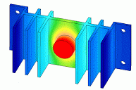
Applying heat deforms materials. It can degrade structural reliability or improve strength. Either way, you want to know the effects heat has. With thermal simulation you can define problem areas and mitigate design weaknesses. Better designs lowers time and costs of prototypes and tests later on.
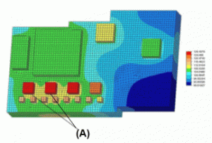
A Printed Circuit Board (PCB) will be subject to a heat generation load applied to the chip. If we want to understand the thermal characteristics of this process we can perform a heat-transfer analysis. How does a simulation like this work and what kinds of parameters are important? What do the results tell us? All these steps are outlined in this article with FEA tools Femap/NX Nastran.
With your model you want to capture important features and gain insight. So you’ll start with a simple model and add complexity until assurance of results validity is reached. By working this way you’ll be able to provide answers in a cost-effective manner. There are three main steps for setting up a FEM model:
For thermal analysis CAD geometry is usually overly detailed. So the first step is to simplify geometry or create new geometry. The latter might not be as cost-effective. The most difficult and important step is applying the correct boundary conditions.

Boundary conditions include, but are not limited to: applied loads, constraints and material properties. For thermal analysis a very important parameter is the material and its properties, in particular its thermal properties such as thermal conductivity. The reason for this is because thermal properties determine the rate and direction of the heat distribution and the locations of the thermal stresses, which is exactly what we’re trying to find out with thermal analysis.

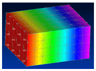
Once the correct boundaries are applied you are ready to run the analysis. After the analysis is done you can check if the deformations are as expected.
At Femto Engineering we work with thermal specialists and specialized tools like the Femap Thermal Solver, Simcenter 3D and STAR-CCM+. If you need help with your thermal issues, don’t hesitate to contact us!
We hope this helps. Thanks for reading! If you enjoyed this article, say hello to us on Twitter, Facebook or LinkedIn.
Do you need more information or want to discuss your project? Reach out to us anytime and we’ll happily answer your questions.
At Femto Engineering we help companies achieve their innovation ambitions with engineering consultancy, software, and R&D.
We are Siemens DISW Expert Partner for Simcenter Femap, Simcenter 3D, Simcenter Amesim, Simcenter STAR-CCM+ and SDC verifier. Get in touch and let us make CAE work for you.
Sign up for our newsletter to get free resources, news and updates monthly in your inbox. Share in our expertise!